Published: Jan 20, 2021 by James K
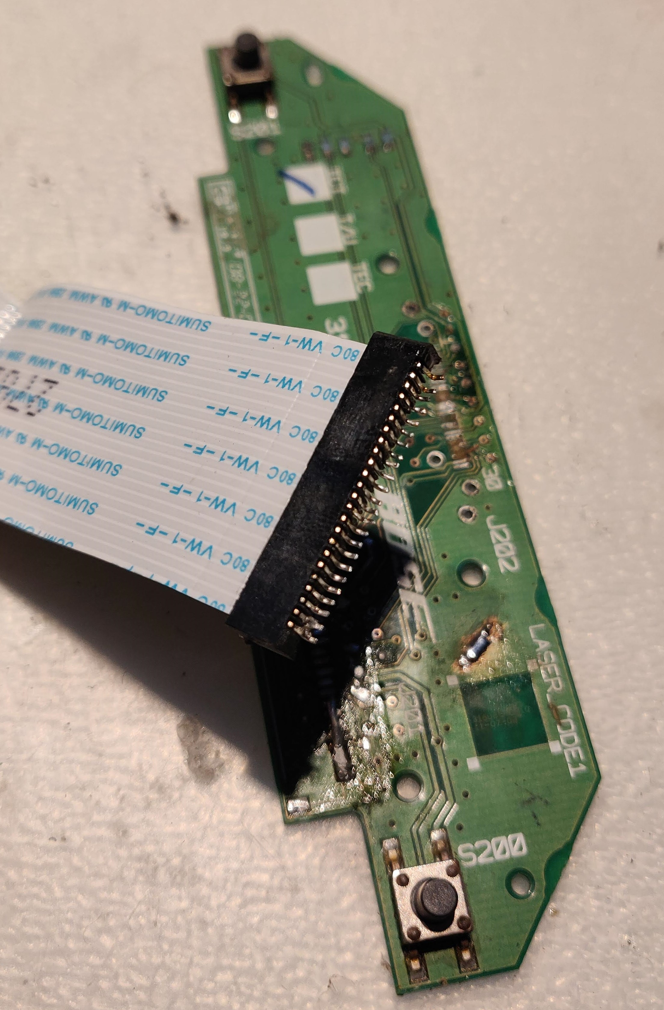
I somehow ended up with this original Bose Sounddock. Its only means of audio input is via a 30-pin iPod dock connector. Notwithstanding that this connector is now really obsolete, the 30-pin dock connector had come off. From my trawling of the internet, this is a fairly common problem.
Now, it was fairly lucky that when this connector came off, it didn’t rip off the copper footprint on the PCB. So I was able to use my Hakko FX-951 iron and re-solder it back on (thanks, Flux!). I dug out my old (pink) iPod nano, and sure enough, the sounddock works again!
But that’s boring…
Turns out it’s quite a decent little speaker! People love to give hate to Bose - Sometimes it’s warranted, sometimes people are just idiots. In this instance, The speaker isn’t bad, and it didn’t cost me anything! I want to do away with the dock connector, and be able to use it with anything - which means I want a 3.5mm Jack socket for the audio input. You can buy adapters, but that’s ugly and lazy.
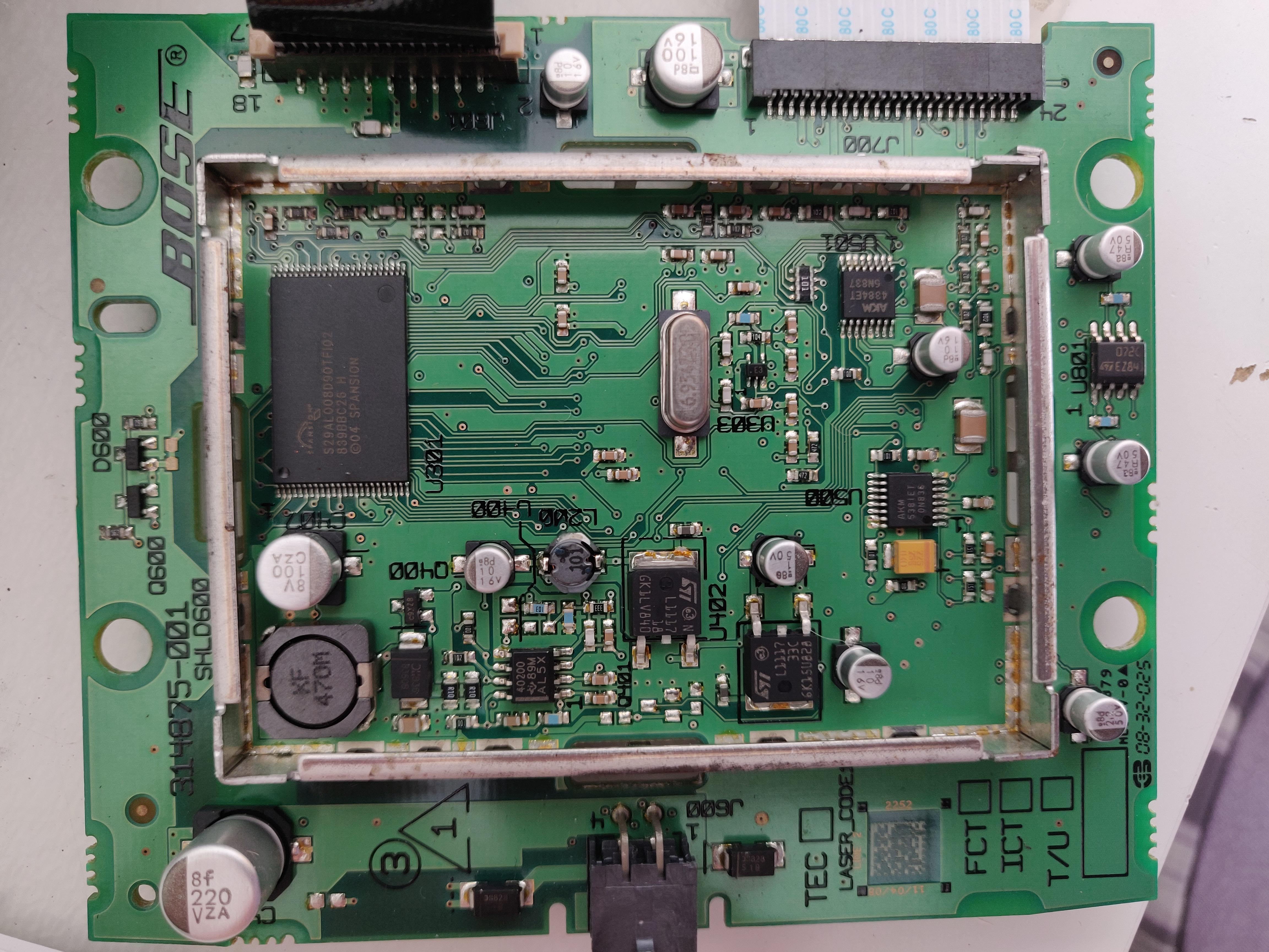
The sounddock only turns on when an iPod is docked (and conversely, off when there is no iPod). This adds a bit of challenge to the hack, but not too much. Thankfully by now, the pin-out of the 30-pin dock is known. The dock board that I repaired also has the volume buttons. This is connected via a ribbon cable to the DSP mainboard. After removing the EMC Shielding Can (couldn’t help myself, don’t judge me!), we can see that this thing is not just a basic speaker.
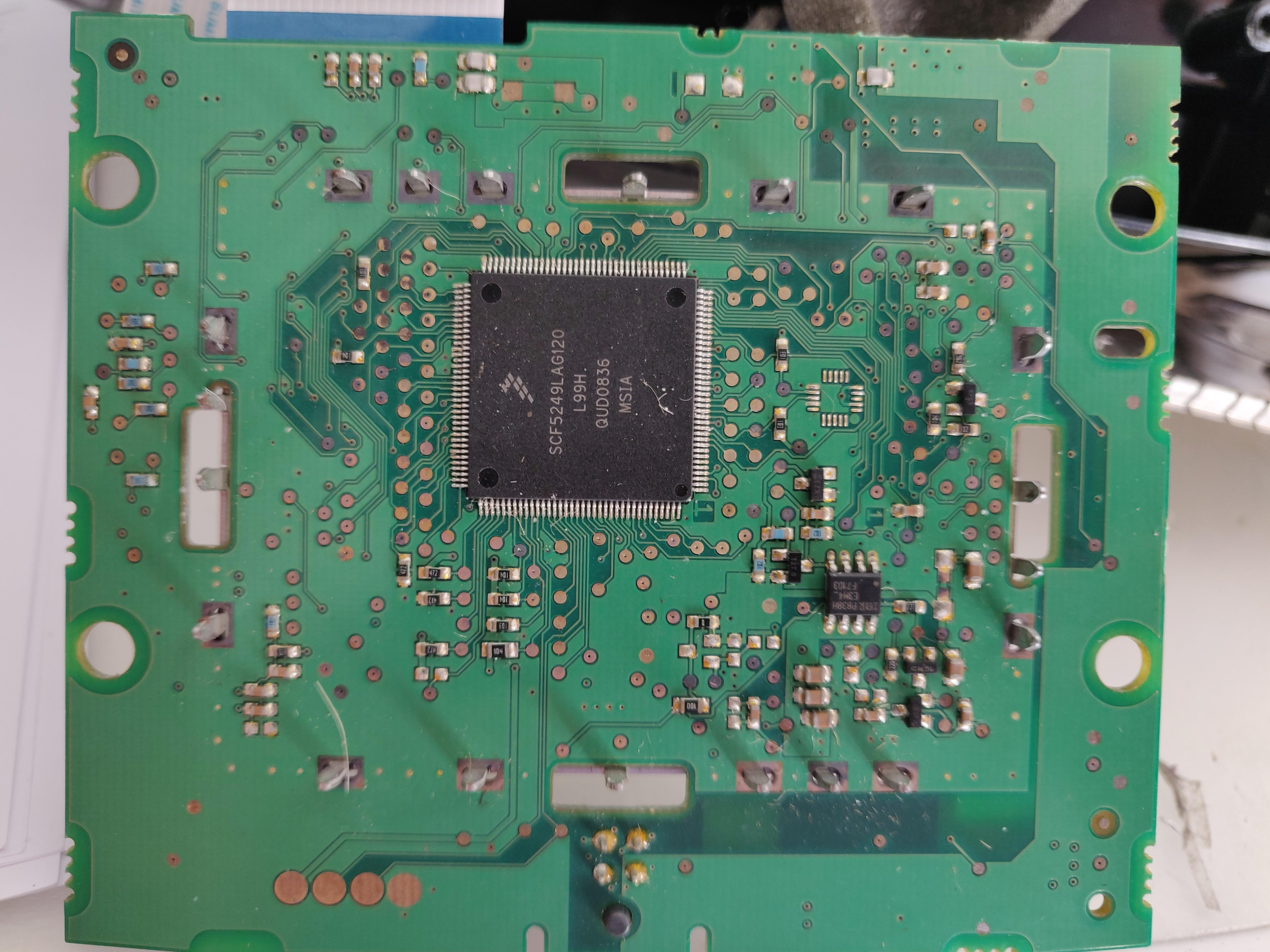
The main board is not the amplifier though, by the way. It has a Freescale (well, NXP now) SCF5249LAG120 on it, which is a ColdFire Digital Signal Processor (DSP) Microprocessor. So this IC is what Bose are using to provide the DSP (e.g. Equalisation, Compression etc.) for this speaker.
An AKM 5381 24-bit Stereo Analog to Digital Converter (ADC) is used to capture the iPod audio for the DSP, and an AKM4384 24-bit Digital to Analogue Converter (DAC) is used to convert the DSP’s output to stereo outputs for the Amplifier board. There’s also a Spansion S29AL008J (again, was bought by Cypress, and then Cypress bought by Infineon) 8Mbit Boot Flash, which is what the DSP will boot from.
This DSP will also be doing some system housekeeping functions as well. For example, this item originally came with an IR remote control, which had volume controls, next track, previous track and play/pause buttons - the IR receiver connects to the DSP board via the Amp board. The DSP will handle the receiving of the IR commands, and will also convert any track control inputs into signals to the iPod.
With a bit of patience, I was able to reverse-engineer the schematic on the dock board. This meant, that armed with the pin-out of the 30-pin connector, I could work out what the signals on the ribbon cable were, and, the schematic of the volume buttons. It was only after this that I discovered a very useful Bose Service Manual that covers upgrading older units from FireWire charging to 5V USB charging. It has a very useful schematic diagram in there of the dock board - Gah! Never mind, it allowed me to double-check that I was right at least! The unit I have already has the 5V charging. With this, I wanted to now make sure I could run this thing with 3.5mm jack source and control the volume, without the dock board. I decided to salvage ribbon connector off the dock board, and make a breakout for it.
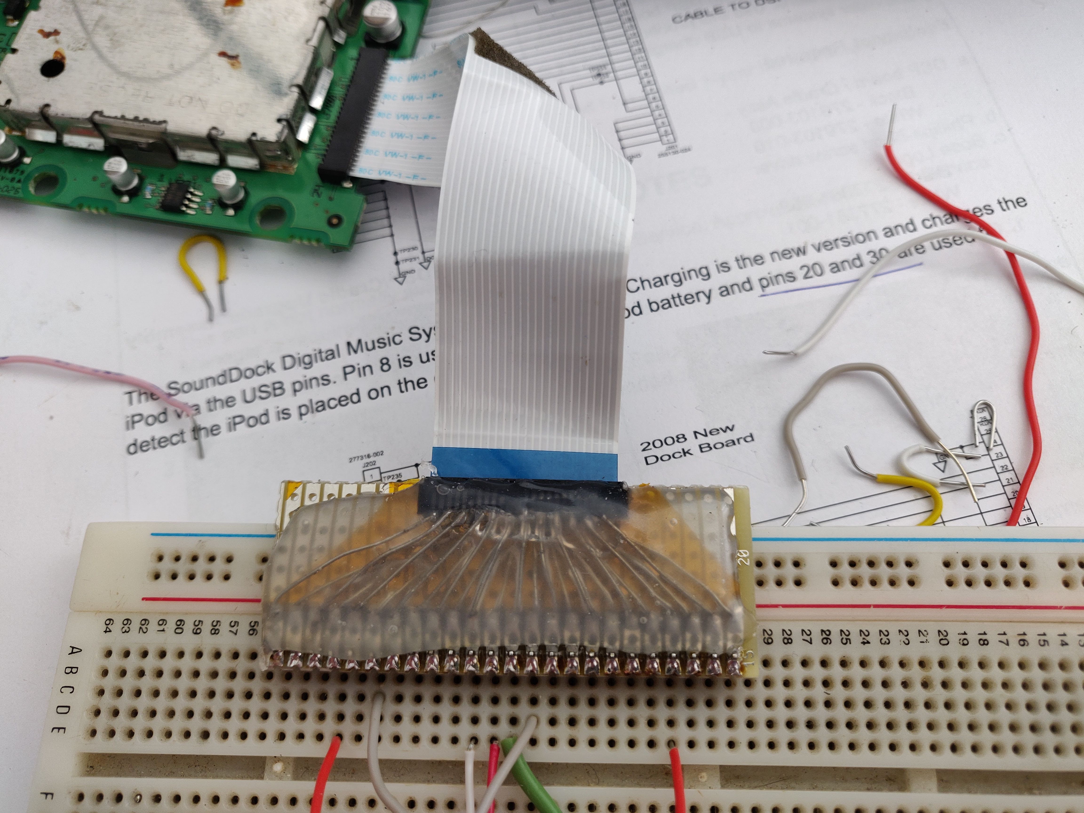
I used the schematic to create a pinout for the DSP board ribbon connector:
| DSP Ribbon Pin | iPod Pin | Bose Schematic Signal | iPod Signal |
|---|---|---|---|
| 1 | 15 & 16 | DGND | GND/USB GND |
| 2 | 15 & 16 | DGND | GND/USB GND |
| 3 | 15 & 16 | DGND | GND/USB GND |
| 4 | 13 | 3.3V from iPod | 3.3V Power |
| 5 | N/A | GND | |
| 6 | 8 | +5V_USB to iPod | 5V USB |
| 7 | 15 & 16 | DGND | GND/USB GND |
| 8 | 15 & 16 | DGND | GND/USB GND |
| 9 | N/A | VOL (- OR +?) | |
| 10 | N/A | VOL (- OR +?) | |
| 11 | N/A | GND | |
| 12 | 29 | AUDIO GND | Audio/Video GND |
| 13 | 28 | AUDIO R | Line Out R |
| 14 | 27 | AUDIO L | Line Out L |
| 15 | 20 | ACC-DETECT | Driven LOW so iPod uses Line Out |
| 16 | 19 | RXD | iPod UART |
| 17 | 18 | TXD | iPod UART |
| 18 | N/A | GND | |
| 19 | 30 | IPOD_DET | GND, tied to pin 29 within iPod |
| 20 | 8 | +5V_USB | 5V USB |
| 21 | 8 | +5V_USB | 5V USB |
| 22 | 10 | ACC-IDENT | Accessory Indicator/Serial enable |
| 23 | N/A | GND | |
| 24 | N/A | GND |
The Service Manual specifies that when an iPod is connected, on the 30-pin dock, Pin 20 (ACC-DETECT) goes HIGH, and Pin 30 (IPOD_DET) goes LOW, which you’d think is what you need to do to make the unit power on - but this doesn’t quite match what I found myself. In reality, there are two conditions that signal the unit to power on when the iPod is connected; first, the “3.3V from iPod” signal is driven high by the iPod, so this can be acomplished by pulling this signal high to the USB 5V rail via a 2K resistor. Although it is 5V and not 3.3V, the worst case current that can flow here is 2.5mA (5/2000), and I cannot see that doing any damage. This The second condition to signal power on, which does align with the service manual, is by pulling IPOD_DET low - This is because in the iPod, pins 29 & 30 are connected to GND, so, when the sounddock sees that pin go low, it knows it is from the iPod being connected.
I tested that this all works using the breakout connector. I now needed to create these power on conditions on the DSP board directly, and find places to tap into for the audio and volume controls. I removed the ribbon connector from the DSP board to make this easier. I was able to place the 2K resistor easily enough, and for the grounding of pin 19, there were very convenient jumper pads already!
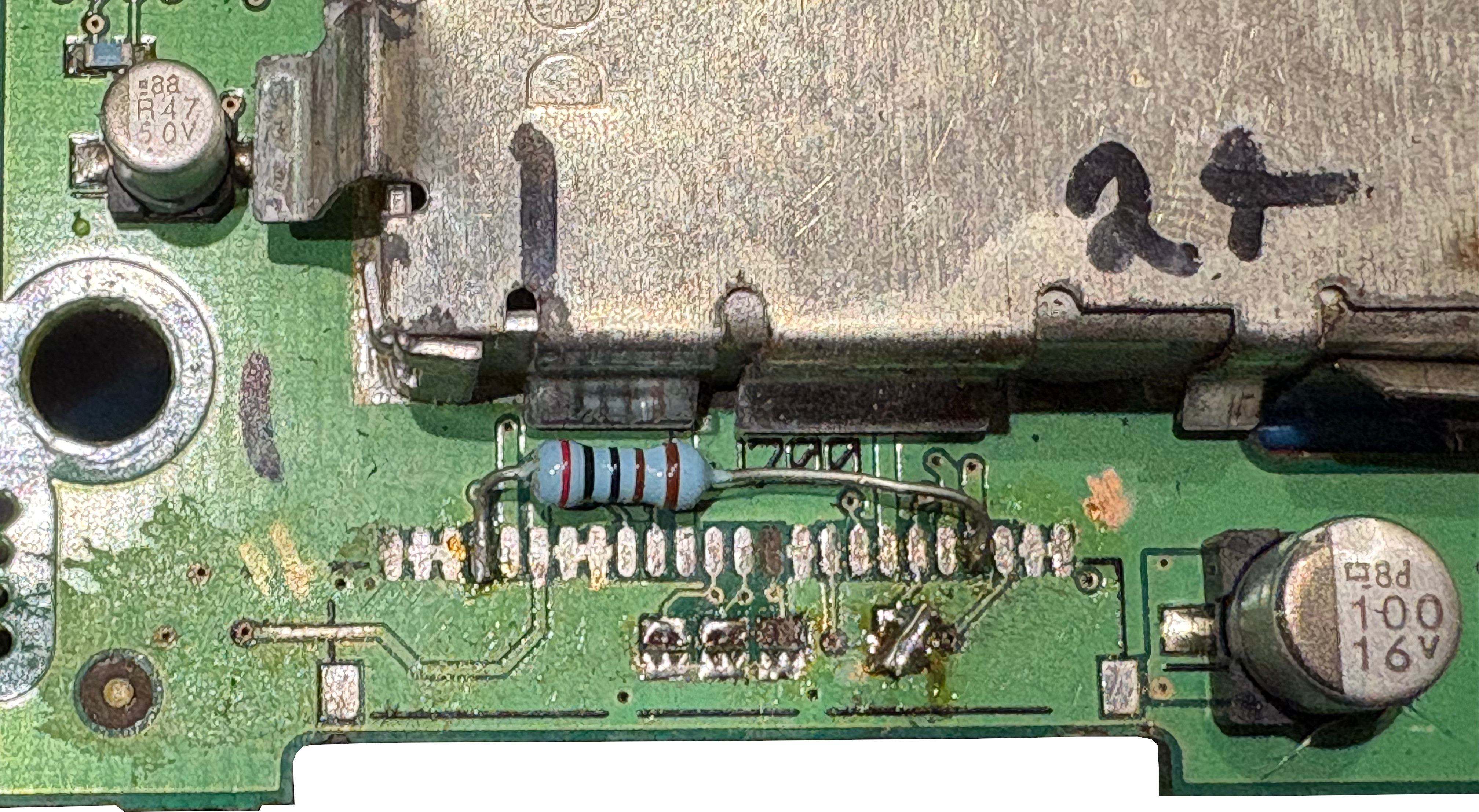
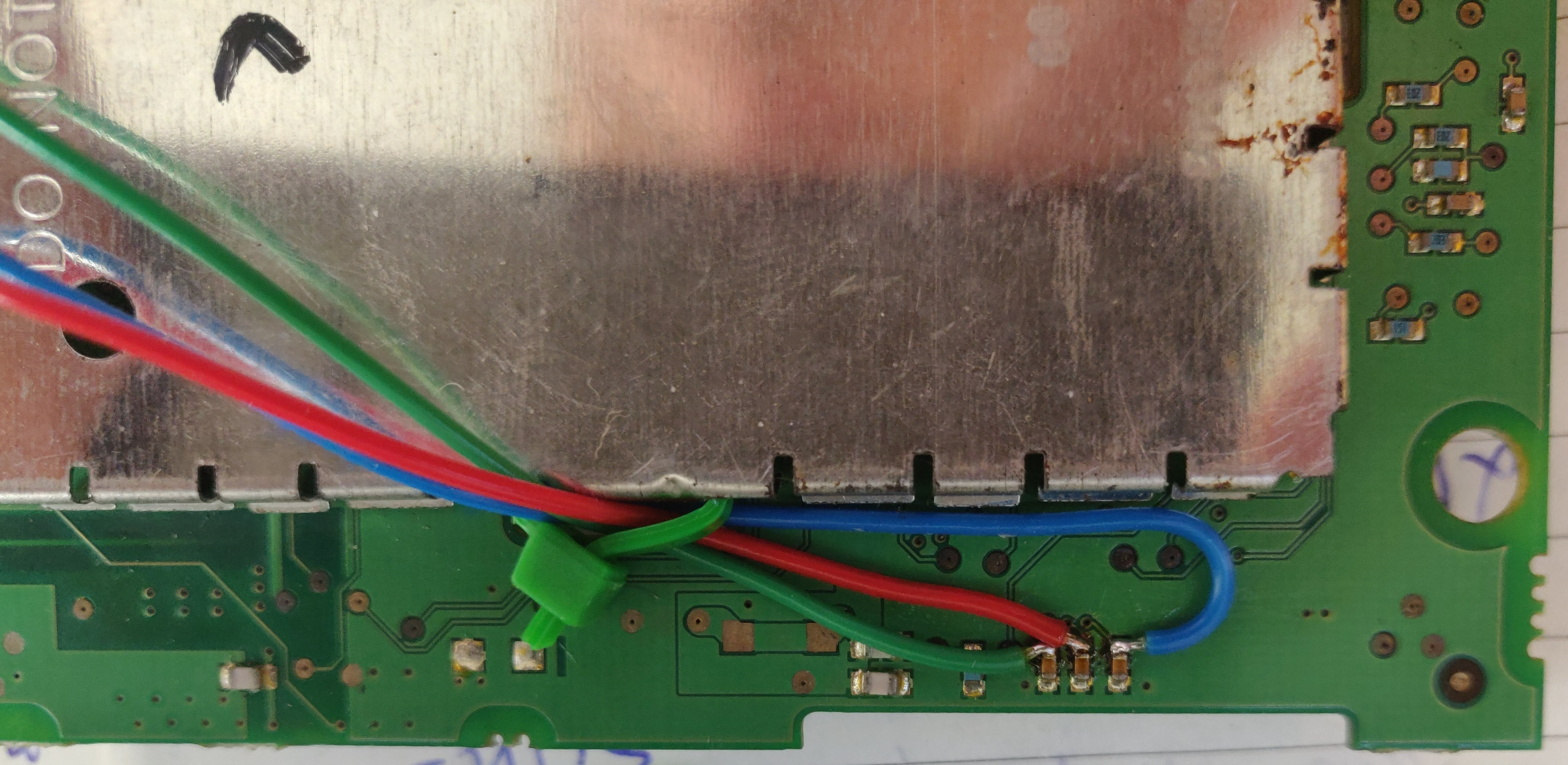
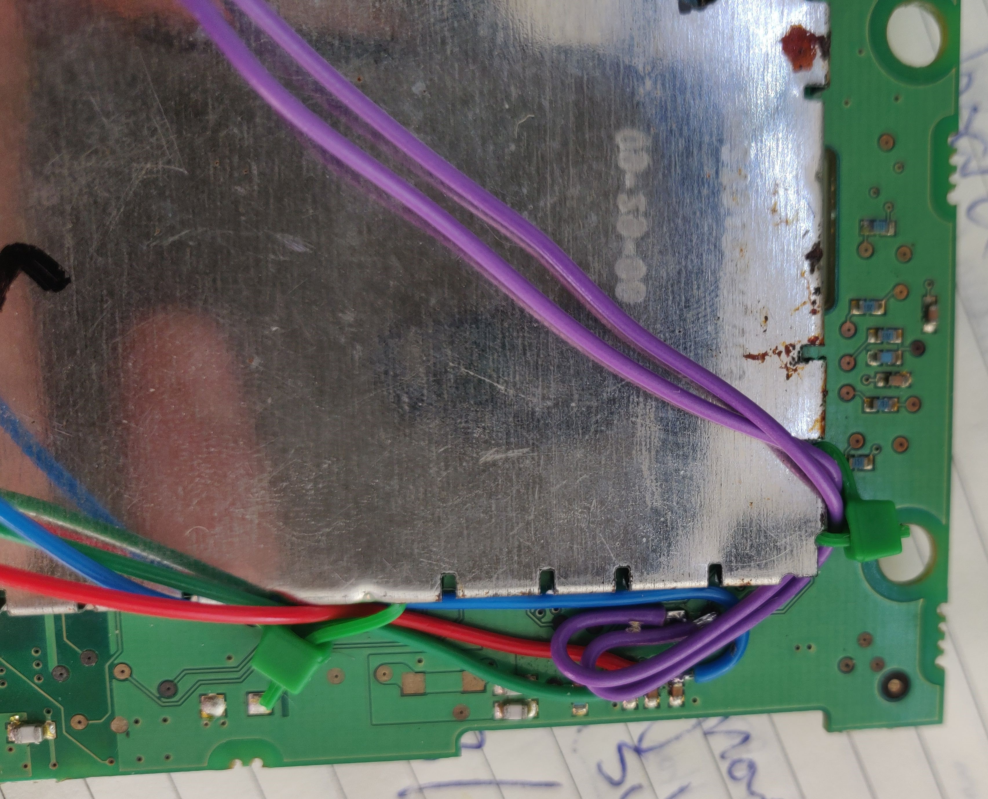
I added a 3.5mm Jack Socket that I salvaged from another board - ideally I should have used a panel mount one, but I only had this PCB mount one to hand. I used hot glue to fix it in place and it is doing fine.
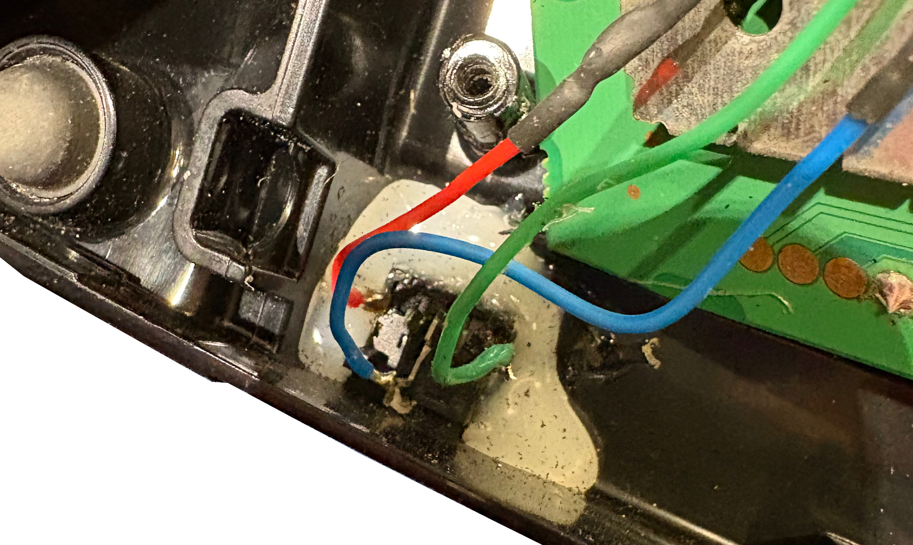
I needed a way to power the unit on and off. I went a bit quick and dirty on this bit! The power into the unit is +18V and -18V. I decided to switch these two power rails using a DPDT switch. Annoyingly the 18V pins are the inside ones on the molex connector! So I had to make the outside pins do a bit of a go around, to be able to access the inside pins. The 18V pins were cut from the PCB, and routed into the switch. The switched 18V rails were then routed back to where they go into the PCB.
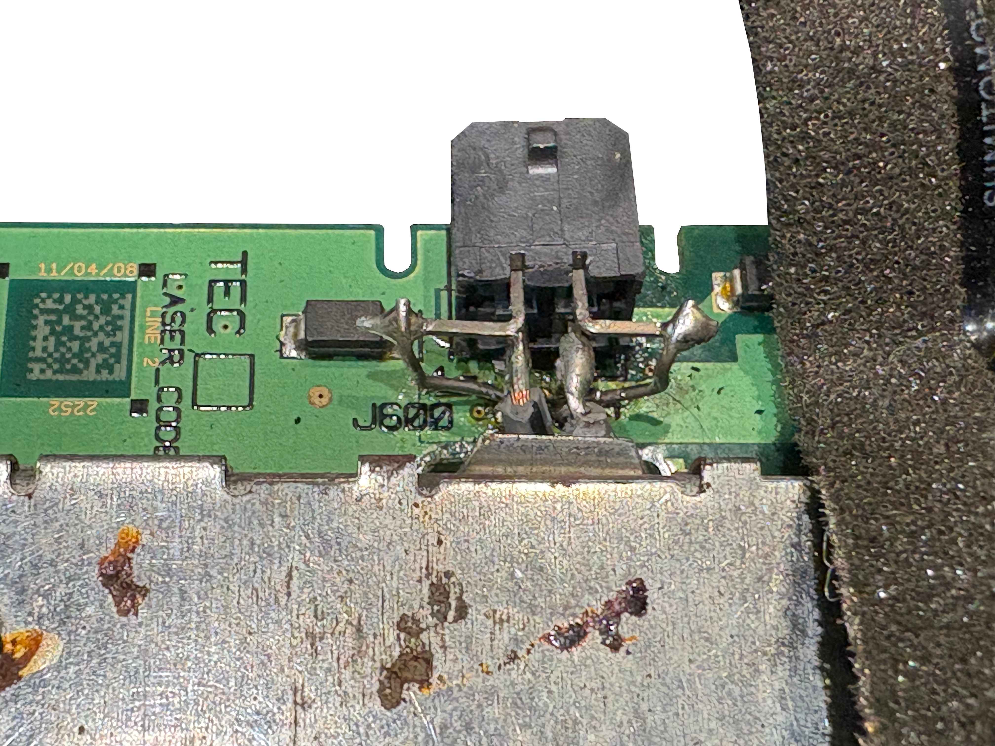
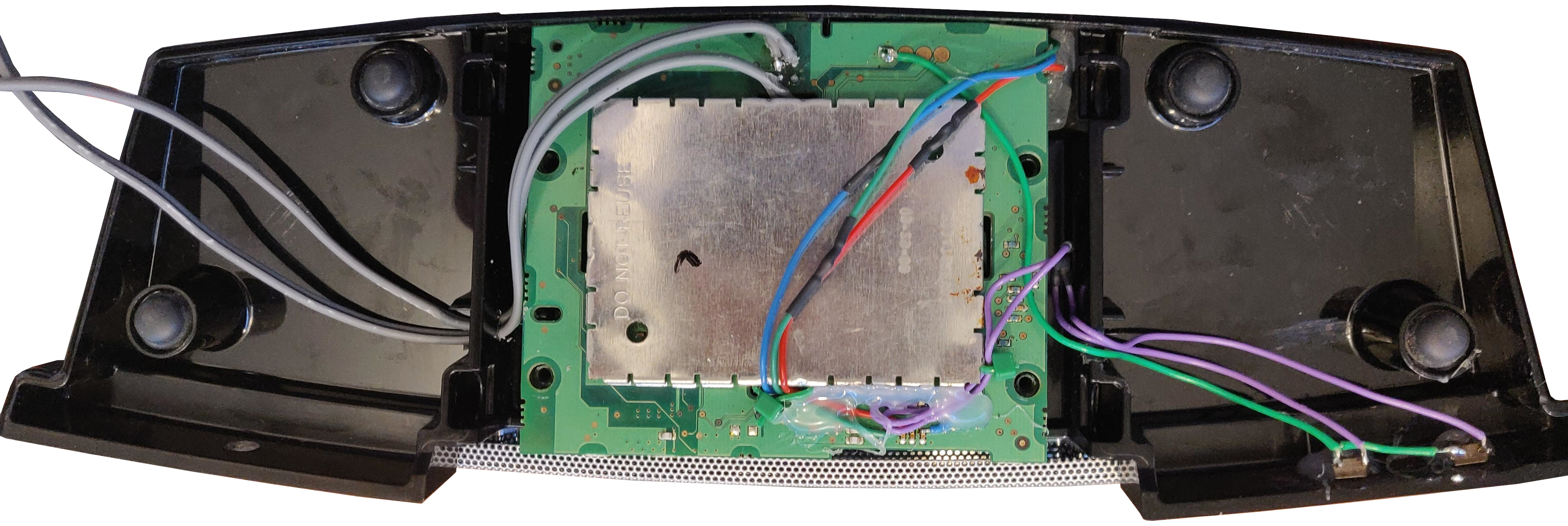
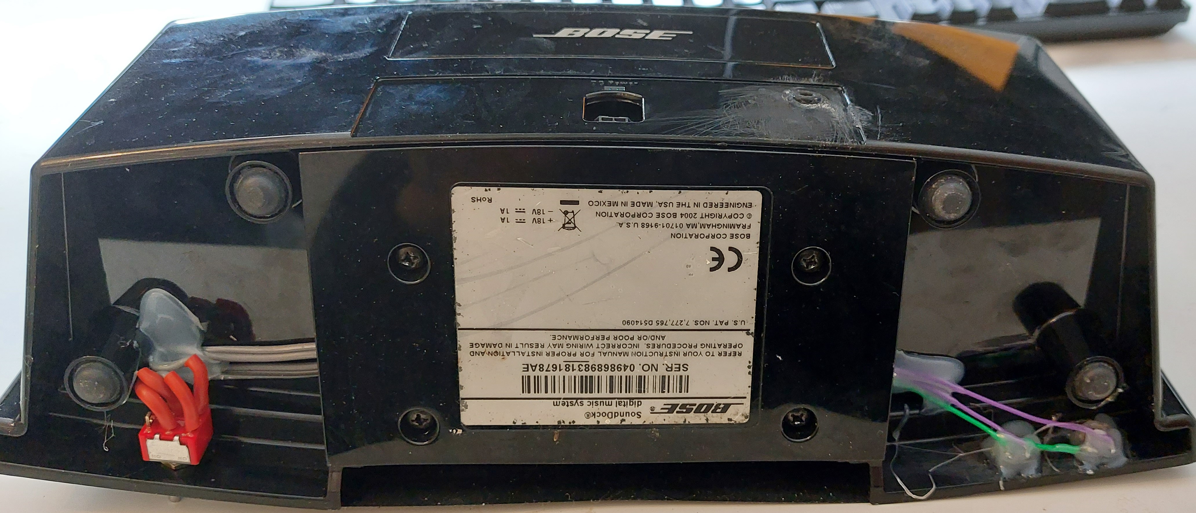
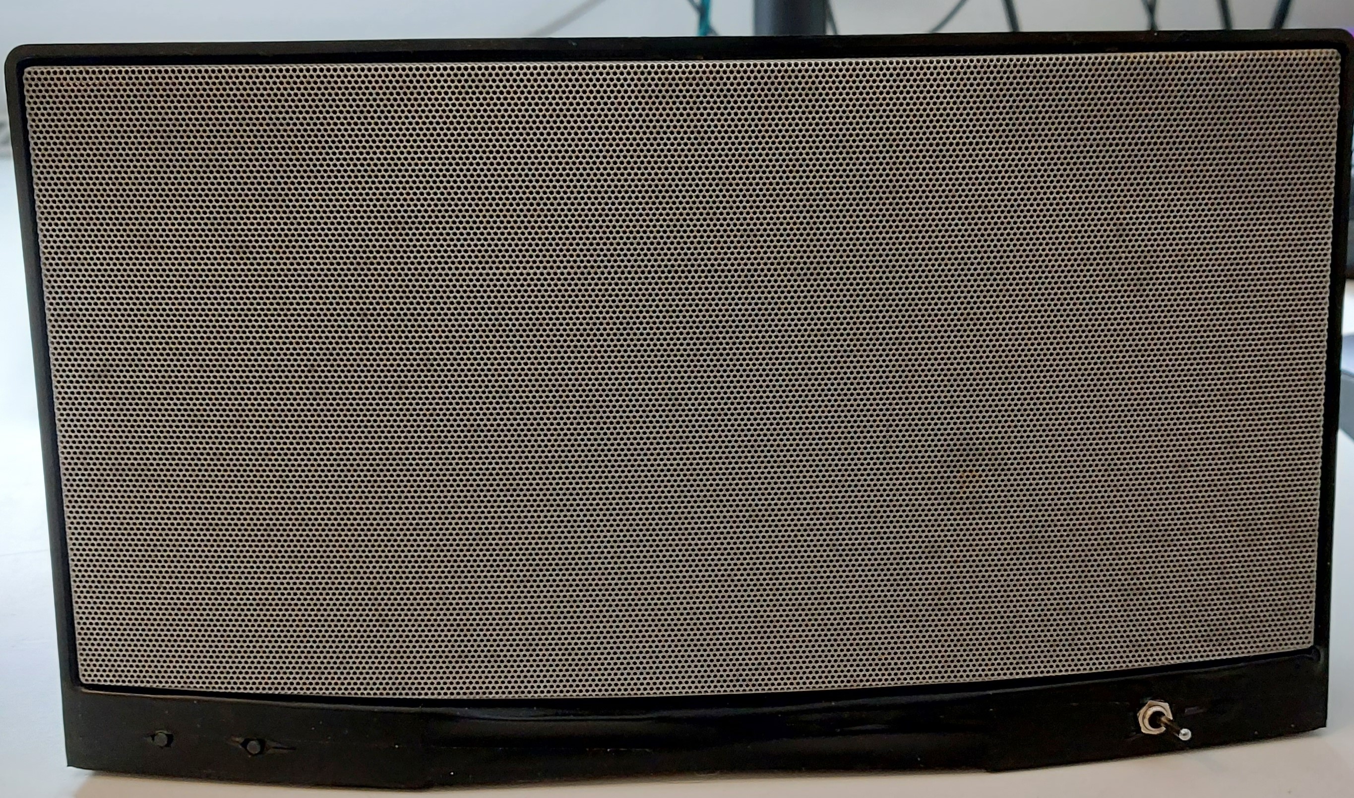
And after all that, I have a Bose Sounddock that takes a 3.5mm Audio Input, and has volume controls on the front! Wasn’t too difficult, and i’m quite happy with it. It comes in quite handy this unit - the sound is pretty decent, and it’s quite loud - the DSP doesn’t start compressing too early.
One to-do here, is to design and 3D print a better base plate that covers everything up. There’s also a gap where the front dock mount used to be, which for now is disguised with black electrical tape. That could be filled in with the new base plate design. I’ll get round to this, one day…
