Published: Jun 29, 2022 by James K
The Canal and River Trust participates in LGBTQ+ Pride Parades all over the country, and they wanted to up their game. They already had an Ice Cream Bike, which they used at various events, and they wanted to be able to transform it into a Disco Bike for whenever they go to pride parades. The idea being that the freezer unit is swapped with an enclosure of the same size, which is a self contained, self powered Public Address (PA) system, capable of playing music loudly. I did this work for them voluntarily, and I’m really pleased with how it turned out. In this blog post, I will explain how it came to life!

Requirements
Firstly and most importantly, The goals for this project are:
Must Haves:
- Have speakers mounted within the enclosure, facing the outside
- Create sound from both left and right of the bike
- Be loud!
- …And be decent sound quality
- Enclosure has artwork, so not interfere with the overall appearance of that
- Self powered from an internal battery
- …which can power the unit for 2 hours
- All be self contained within the freezer-sized enclosure
- Be built within a budget of £500
Nice to Have:
- Incorporate LED lighting for extra “wow”
- Built in battery charging capability
- Easy way of determining the battery level
The Plan
The enclosure was made by the manufacturer of the bike, and has some nice Canal & River Trust branding with a snazzy LGBTQ+ flair! Externally, the dimensions are H: 680mm, W: 540mm, L: 870mm.

The first thing to consider is how it is powered, as this will dictate a lot of the system. It needs to be operated for at at least 2 hours, so this will require a hefty battery. I decided to use a deep-cycle leisure battery that is intended for use in motor-homes and caravans, due to it being able to sustain large loads over a prolonged period of time, and the battery chemistry generally being able to handle deep-discharges. In comparison, a standard car battery is not suitable here; they are designed to give a very short burst of current to the starter of a car, and then more or less immediately get recharged by the alternator - not long use, and not deep-discharges. In addition, leisure batteries come in much larger capacities than car batteries, at the expense of a larger size.
I settled on a NUMAX DC25MF 105Ah Sealed Leisure Battery. This is a NCC Class B battery, meaning that it can handle deep discharges well, since it is capable of at least 200 discharges to 50%.

Since we now know that we are dealing with a 12V system, next is to decide on the main audio components. The car audio market was the easy choice here, since:
- It is designed for 12V systems
- There is a vast selection of parts available
- Audio quality is key in this market
- Thanks to the target market, loudness is also catered for
- Panel mount, which is very install friendly
In car audio, you can either power the speakers using the built in amplifier of a head-unit, or, you can have separate amplifiers for loud systems - this is what I am going to use in this project, separate amplifiers. Since amplifiers are available in 4-channel types (front and rear), I decided to exploit this to be able to install 4 speakers into the system, to achieve the “loudness” requirement.
Simplistic overview of car audio speakers
At the basic end of the scale, you have just one speaker per channel, which is an all-range driver, i.e. doing the bass, mids and high frequencies. Typically, it excels in neither. At the mid range, each channel will have two drivers - a speaker doing the bass and mid range frequencies, and a separate tweeter doing the high frequencies. Bookshelf speakers have a similar approach. At the high-end of the scale, you have the same components as the previous (mid), however, a high-pass filter is used to prevent the speaker from attempting to produce any low frequencies - which allows it to produce better sound without bass encumbering it. To reproduce the low frequencies (bass), a separately amplified bass sub-woofer is used. Usually, this is only one, since low frequencies are not directional and there generally isn’t a concept of “stereo” with low frequencies. …This list is not fully exhaustive by the way! But it is a good general overview of the most common implementations of car audio.
Since I want to accomplish the requirement of “decent sound quality” and “loudness”, I decided to go with the “high end” approach, i.e. I want to have four amplified channels producing the mids & highs, and then one amplified channel for a subwoofer.
So to produce the mids and highs, a mid range speaker is coupled with a high-frequency tweeter speaker, and a suitable cross-over circuit is used to provide the tweeter with a high-pass filtered signal. These two speakers are separate, but thankfully in the car audio market, coaxial speakers exist - these are speakers with tweeters mounted in the middle, which makes installation easier. These seemed like the best choice for a clean installation.
Speaker and Amplifier Choices
When choosing the speakers, it was a difficult balance between finding speakers that are suitably sized for the loudness requirement, that could be installed in such a way that it did not interfere with the graphics on the enclosure. I made a 2D model of the enclosure faces in Microsoft Visio (don’t judge, I have to use it aaaallll the time at work) to be able to play around with different speaker options. The design that I settled on is shown below:

The mid-high coaxial speakers used here are oval! The graphics on the enclosure had some empty space that I wanted to use, and these oval speakers utilised this space the best versus round speakers, since I did not want the speakers to interfere with the graphics on there. The speakers chosen here are In Phase XTC69.3 6x9” speakers, technically they’re 3-way triaxial, as there are two different tweeters in there, nice! Each speaker has a peak power handling of 260W. Since these four speakers will have the low frequencies cut, they should be capable of being loud.
For the subwoofer, a JBL Stage 810 8” Subwoofer was chosen. This has a peak power handling of 800W at 4ohms, and a frequency response of 38Hz to 200Hz. Most importantly, JBL publishes the Thiele-Small Parameters for this speaker, which means that I am able to design the subwoofer enclosure properly using speaker modelling software.
To power the four triaxial speakers, a Juice JA1504 was chosen. This is a four channel amplifier with a peak power of 1500W, which is 375W per channel - this is higher than the peak power handling of the speakers, don’t worry, I account for this later! This amplifier has a built-in high pass filter (HPF) for all four channels, which is important, since I want to cut lower frequencies that are handled by the subwoofer.
To power the subwoofer, a Juice JA902 was chosen. This is a two channel amplifier with a peak power of 900W. This amplifier is bridgeable, meaning I can have both channels drive the single subwoofer as one channel. This amplifier has a built-in low pass filter (LPF), meaning that I can cut all the high frequencies handled by the other speakers, i.e so it functions as a subwoofer.

You may have spotted some extra items in that image, there’s a controller for RGB LED strips there which has a sound-to-light mode. The plan is to put the RGB LED strips on the vertices of the enclosure. There’s also a suitable battery charger there too, which will be permanently fitted within the enclosure so that it is easy to recharge it.
Mechanical Design
Next thing is to get an idea of how the inside will be constructed. The bottom needs an enclosure for the subwoofer - the width is fixed by the enclosure, and the height will be fixed by the height of the triaxial speakers. There is a little bit of flexibility in the depth, however enough size needs to be reserved for the battery. As well as the subwoofer enclosure, the triaxial speakers also need an enclosure too - this is quite important, the enclosure that speakers are in make a tremendous difference to both the quality and loudness of a speaker. (In fact, it was interesting when looking at the reviews of these speakers - most of the reviews said that they were very good, especially for the price. Some reviews said that they were terrible - I can only imagine that it is the enclosure of the door that they are fitted to (for car use) that is letting them down). I used SketchUp to come up with a plan for the internals, which was being built with MDF sheets.

Subwoofer Design
With this design plan, I now needed to design the subwoofer enclosure. I used WinISD by Linearteam, this was the first time using this, so was a learning experience for me. By entering the Thiele-Small Parameters that JBL published, I was able to model the subwoofer enclosure. I settled on making the enclosure a particular volume (which I can’t remember), with a tuning frequency of 35Hz. I found that having two bass ports gave the best performance, and WinISD informed me that their length should be 7.24cm long. Through this simulation, I noticed that the subwoofer was working particularly well below the tuning frequency of 35Hz. Conventionally, this would be a good thing, a subwoofer that can go really low is usually sought after. However, the end use of this is outdoors in an already loud environment, and so the low frequencies would be lost here, and would not add a huge amount of benefit. Most importantly, bass reproduction is quite power hungry, and I do not want to waste power where it can be avoided. For this reason, I decided to use a HPF to cut out frequencies below ≈33Hz - more on this later!
With the HPF added into WinISD, this resulted in a working bandwidth of ≈31Hz to ≈59Hz for the subwoofer (-3dB Point).

Other key parameters that were considered in this subwoofer design were Sound Pressure Level (SPL), Cone Excursion, Port Air Velocity and Port Gain.
SPL is a measure of loudness:
, and then had a uniform SPL from ≈50Hz to ≈126Hz.")
Cone excursion is how much the speaker cone moves; too much excursion risks damaging the speaker. The detail in speaker design is getting the most out of the least amount of excursion. I sound like a speaker expert here, and I’m not! I’m just trying my best to make this subwoofer not suck.
. Therefore, the overall power delivered to the subwoofer speaker will need to be limited through gain limiting.")
Port Air Velocity shows how much air is being pushed and sucked out of the bass port. When this is too high, you get “Chuffing”, which is undesirable noise caused by the sheer amount of air being moved. It is best to keep this below 18m/s. My simulations showed that this was exceeded at the tuning frequency of 35Hz at 35m/s, but rapidly reduced to below 18m/s by 36.8Hz. Since I couldn’t improve this, I decided to hope for the best when I build it, and adjust the HPF if needed.

…By the way, when I did this work, my Windows laptop was out of action (Dell can go to Hell). So I ended up using WinISD on my Mac using CrossOver by Code Weavers. Worked really well!
Building Commences
I adapted my SketchUp drawing to make the enclosure, and started building it.


I then created the enclosures for the triaxial speakers, and added the RGB LED strips to the edges. The LED strips were self adhesive (supposedly 3M adhesive, if that can be trusted), but I was taking no chances here, so I also used clear Sticks Like Sh*t Adhesive (at the time of writing, this is still called “Sticks Like Sh*t, however when I see it in the stores, it has been renamed to simply “Sticks Like”…).

I deviated away from the original plan with the mounting of the amplifiers, and decided to stack them recessed a little bit into the gap between the triaxial speaker enclosures. I also made a place for the battery to sit so that is is not loose.
To drive the RGB LED strips, I just used some generic controller box that I got from AliExpress. It has built in patterns and two sound-to-light functions using a built in microphone. Importantly here, the controller has a potentiometer to adjust the sensitivity, which is important, since the sound that the microphone will pick up will no doubt be very loud inside the enclosure!


I’m quite keen on keeping wiring neat and tidy, so at this point, decided to neaten up the wiring. Also, I removed the potentiometer from the LED Controller PCB and extended it on some wire so that the sensitivity can be adjusted easily - you’ll see how later on…
")
Infrasonic Filter PCB
With the majority of items now fitted, it is coming to the finishing touches-stage. As previously mentioned, I want the input signal to go through a HPF to remove the super low frequencies that are not necessary. Cutting these very low frequencies would not be noticeable, and would save on power, with bass being power hungry. Since I was pushed for time here, and did not want to reinvent the wheel, I looked to the internet for some inspiration. Thankfully, I came across this Infrasonic Filter by Elliott Sound Products. The main project itself is for a -3dB point at 18Hz, however I wanted this to be about 35Hz. Thankfully, the -3dB frequency is adjusted by changing the value of capacitors C1 to C6, and the project page details the value of capacitor for different -3dB frequencies. So, using 82nF for C1 to C6 should give me a -3dB point of 33.2Hz, which is close enough.
I love using LTspice whenever I can, so I decided to simulate this Infrasonic Filter, using the 82nF capacitors. The project page lists some recommended op-amps, and so I had a look in my parts bins (my partner calls it parts hoarding…) and I had some of the recommended Texas Instruments OPA2134! Nice! They’re actually a Burr-Brown part, which is known for being quality. So I decided to simulate with this. Thankfully TI provide the SPICE library for this part, so it was not difficult to import the SPICE model into LTspice.

It seems that most of the time when I am using LTspice, I am running transient simulations (time-domain simulations), so this simulation was a great opportunity to use LTspice for AC analysis (frequency-domain simulations). I set the simulation up to analyse the attenuation of the output with respect to the input signal, over a frequency range of 0Hz to 1kHz. What I found, was that the -3dB point was ≈33.7Hz; not too far off the stated value of 33.2Hz! So this Infrasonic Filter should be the ideal HPF for my needs here. (I did also double-check that there was no attenuation above 1kHz too).

Now I needed to turn this design into a reality. Usually for one-off boards like this, I turn to stripboard/veroboard, but I decided to be more professional and design a PCB for two reasons: 1. I wanted the traces to be as short and neat as possible, so that the real thing matches the simulation (I was concerned of stray capacitance / inductance from the stripboard having a negative effect), and 2. I wanted it to look professional! I designed the Schematic and Layout using KiCad.
To provide the +15V and -15V rails, I used a XP Power ITV1215S DC-DC converter module. This takes in the battery voltage, and converts it to +15V and -15V in a nice neat package.

Since I was pushed for time at this point (I was in the middle of moving house while doing this - this bike enclosure box was literally the last thing left in the house!), I did not have time to wait for PCBs to be manufactured, so I decided to go old-school and etch the PCB myself, since I already had the tools and equipment - this means that I had to design it as a 1-layer board. I managed to do the layout with only 3 jumpers needed, which I was really pleased about.

Sadly I did not get any photos of the etching process, but there’s nothing novel going on here, so you’re not missing out on anything. I used copper clad board that already has the photoresist layer - you just have to peel back a protective film. This makes the process a lot easier. And for the etching, I used classic Ferric Chloride.

Now, when I designed the PCB, the only 82nF capacitors I had were some SMD ones - this is no issue, it’s easy enough to mount SMD capacitors as though they are through hole, you just have to have through holes that are the length of the component. Using these holes, you solder some tinned copper wire in the holes, trim down, and then solder the SMD part onto those leads. Well, that was the plan, but clearly I cannot count - I only had 10 of those SMD 82nF capacitors, not 12! So silly of me. Since I was pushed for time (house move still ongoing!), I decided to see if I could remedy this. Thankfully I did have some other 82nF capacitors, I think they were polyester ones, versus the multi-layer ceramic SMD ones, but they were through hole and quite big - certainly bigger than I had designed for. Very annoying. But, I made it work!

I now wanted to test it out, to make sure that it worked. The best way would have been to evaluate the gain vs frequency, to get a graph similar to the one obtained in the LTspice simulation. I didn’t really have the correct equipment to do this (bit outside of the capabilities of my home lab). So I did it a different way. Firstly, without the Infrasonic Filter installed, I used a frequency generator to listen to the reproduction of frequencies between 1Hz and 50Hz. Then, I installed the Infrasonic Filter and repeated this frequency sweep, and as expected, there was nothing at all until just below the -3dB point of 33 to 34Hz. Amazing! To double check, I played some music to make sure that it is not having an impact, which it wasn’t.
Final Touches
With most of the enclosure now done, I now needed to tidy up the inside and make it easy to use, and maintenance free. I mounted the battery charger inside (so that it does not go missing!). But I needed to address the following needs:
- A way to switch between OFF/battery charging and ON
- A way to turn the speakers on/off via the on/off trigger input of the amps
- A way to turn the LEDs on/off
- Somewhere to mount the sensitivity pot of the LED controller
- Somewhere to mount the remote controller for the LED controller
- A way to see the battery state of charge
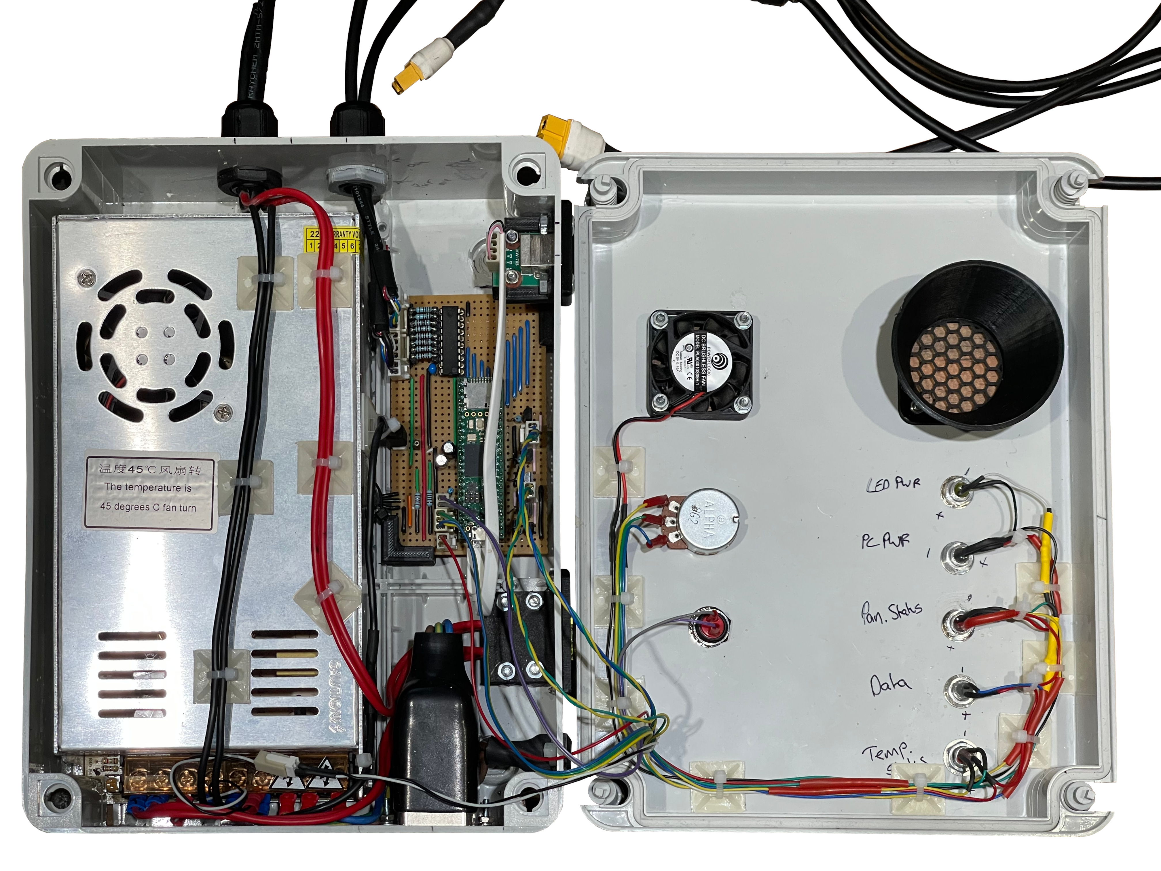
I went a bit above and beyond here, and I made a control panel that sits inside the enclosure. The LED Controller has a remote control, that I wanted to mount on the control panel so that it doesn’t go missing. I hacked this a little bit - I removed the Infrared (IR) LED from the remote control PCB, and put it on a small length of wire, so that I could make sure the IR LED points at the IR receiver in the LED controller. The sensitivity potentiometer mentioned earlier also got mounted on this control panel.

And here is where I got a bit carried away… I decided to use a small LCD screen that I had sat around, with the intention of using it do display the battery level. Since I was rushing a bit at this point (moving house!), I used an Arduino Nano. Remember how I said earlier that I made a PCB because it looks more professional than stripboard? Well, I used stripboard to make the microcontroller board. On here, was a potential divider and voltage follower, to allow the Arduino to measure the battery voltage. But I went a bit mad here, and decided to add in some current shunt resistors to allow the current consumption to be measured as well! It might be a bit extra, but I think it’s really cool!

And here is the finished bike!

Requirements Check
So now is the time to evaluate if I met all my requirements…
Have speakers mounted within the enclosure, facing the outside
Yes - Four speakers mounted within.
Create sound from both left and right of the bike
Yes - two speakers on each side to create near-enough 360° sound.
Be loud!
Subjective, but Yes - I tested this outside in my street and it got all the neighbours outside to see what was going on! And the real proof, is when this was finally used for Pride Parades, and the feedback I got was that it was plenty loud enough for them.
…And be decent sound quality
Again, subjectively Yes - I am quite particular about sound quality1, and considering I did this on a budget, I think it sounded as good as a quality PA system. By not overwhelming the main speakers with producing lower frequencies, and using a good subwoofer, the sound was something I was happy with. Which was a relief!
Enclosure has artwork, so not interfere with the overall appearance of that
The four speakers and subwoofer grill and port are placed such that they don’t interfere with the graphics on the enclosure.
Self powered from an internal battery
Yes - used a quality leisure battery which is intended for prolonged use.
…which can power the unit for 2 hours
Yes - proof is in the pudding, in that this lasts just over 3 hours when used in a Pride Parade. This is helped by the use of an Infrasonic Filter (HPF) to cut wasteful lower frequencies that would use power with no real benefit.
All be self contained within the freezer-sized enclosure
Yes - everything is securely mounted within, in a tidy manner too.
Be built within a budget of £500
YES! The total cost was £498.96, a whole £1.04 left over. Super pleased with this. But I did spreadsheet the whole project while designing it, and parts were chosen to fit this budget. I do need to ‘fess up here though, that I’m not factoring in things like Solder, Miscellaneous wire, nuts and bolts etc., which I have on stock. Also, the control panel was built entirely out of parts that I already had in my collection of parts that I have in my parts bins and trays (my partner would call it hoarding, but I disagree!). I was happy to use these parts and give away to the Canal & River Trust.
Incorporate LED lighting for extra “wow”
Yes - LED Strips mounted on all vertices of the enclosure, that have sound-to-light feature - looks great!
Built in battery charging capability
Yes - A 12V Battery charger is built in to allow the battery to be charged easily, and also so there is never a “where’s the battery charger?!” moment.
Easy way of determining the battery level
Yes - went a bit extra with the control panel, but it gives a really easy way to see the battery state of charge.
-
For a bit of justification to this, back in 2018 I managed to get a new BMW 3 Series (you can see it in the photo above actually!), which was great, but the standard sound was truly awful. I was going to have the car for the next 4 years, and didn’t like the idea of having to deal with the poor sound for that long. So I removed all the seats, trims and door cards, replaced the speakers, fitted some tweeters into the A-pillars, and installed a DSP-Amplifier with some new wiring looms that I made myself. And also sound-deadening sheets applied to the inside of the doors. Re-coded the head unit to output a non-amplified flat-EQ and tuned the DSP as best as I could. Oh, and put the car back together again! The result sounded incredible! And I could crank it up too. Was really proud of that, had a beautiful 4 years of sound and driving with that car. I still miss that car… Maybe I will do a blog post on this one day! ↩