Published: Oct 15, 2025 by James K
OutdoorLads LED Matrix
A three-part build exploring the design, hardware, and firmware behind a portable LED matrix for the OutdoorLads DJ booth.
- OutdoorLads LED Matrix (Part 1: Concept & Design)
-
OutdoorLads LED Matrix (Part 2: Build & Hardware)
- OutdoorLads LED Matrix (Part 3: Firmware, Software & Showtime)
In Part 1 I covered the design journey. Now let’s get into the physical build — frame, panels, wiring, and power.
Driving the Pixels
Now that the physical aspect of the design has been realised, albeit in 2D CAD, I now need to design a system for driving the pixels. As mentioned, I’m familiar with addressable LEDs, I’ve used them quite a lot in the past. But, I have always driven them in a single chain from one output on a microcontroller. This design has 624 pixels - it certainly isn’t a crazy amount, like Design B was, but this is a significant amount of pixels and I want them to be able to refresh quickly to be able to display the effects nicely.
And speaking of effects, where are these going to come from? Well, while doing my research for this project, I found the Jinx! Application from live-leds.de - this is a super powerful piece of software for driving LED Matrices - it has a tonne of built in effects, plus you can create your own too using the existing effects as building blocks. And it is free! This seemed perfect. It does mean that the effects are created on-the-fly by a PC, with numerous connections/protocols available. So with this, I need to build some hardware that sits in between the PC and the LED Matrix.
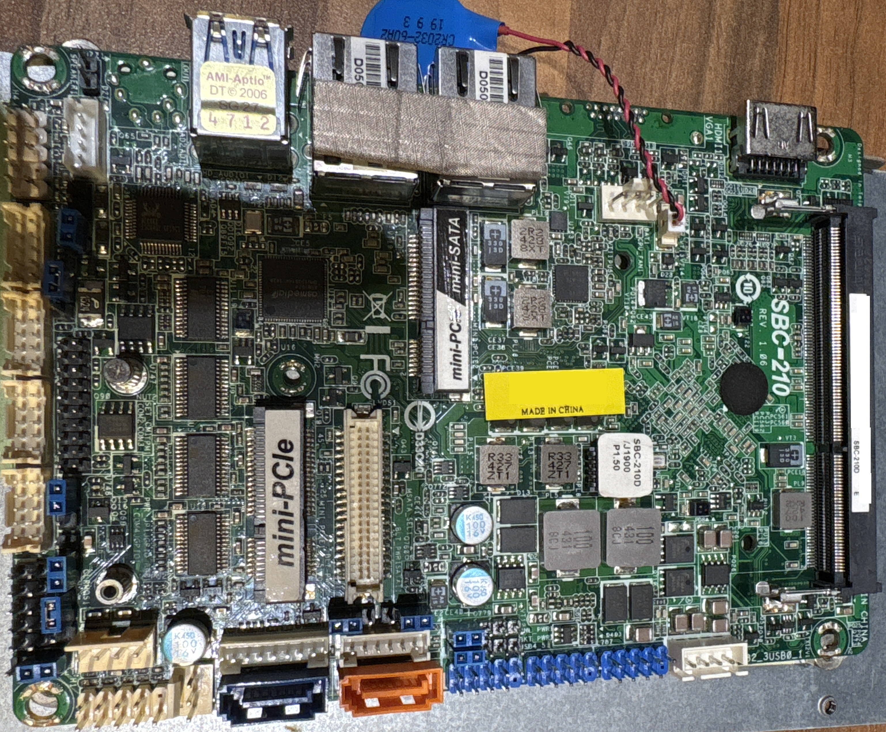
Speaking of the PC, I was chatting about this project to a friend, and he very generously donated me a Dell Venue 5130 tablet. Annoyingly, this has an Intel Atom 64-bit processor, but Dell in their wisdom have never released BIOS for 64-bit operation, so it is stuck in 32-bit mode! Not to worry, shouldn’t be a problem. I used Windows 10 Debloater to strip out unnecessary bloat in Windows 10.
So, I need to build hardware needs to receive the effects from the PC, process, and output the addressable LED signal with WS2811 protocol, and power all the pixels. So how to drive the pixels? My past use of addressable LEDs have always been quick projects with low pixel count, so I have got away with using an Arduino, but an Arduino can only really drive one output channel at a time. You could spread them out onto different channels, but there is not a massive performance change with this. Let’s crunch some numbers:
It takes 30 μS to update one pixel, so with 624 pixels on one channel (i.e. all one continuous string), it takes 19 mS to update all pixels. That means that we would have a refresh rate of 53.4 fps. On the face of it, that is not too bad - to put it in perspective, the refresh rate of a typical LCD is 60 fps. There is a big but here though - this is assuming that the microcontroller is doing nothing at all other than updating the pixels. This is simply not going to happen - the microcontroller is going to be receiving the live stream of data from the PC, processing it into a pixel map, and outputting with the WS2811 protocol. Plus this doesn’t even consider any housekeeping functions that I will probably have too. So, the theoretical value of 53.4 fps isn’t going to be realised with this approach, and this doesn’t factor in the 16 MHz clock of an Arduino.
But not to fear, I had something in mind all along! Enter Teensy 4.1! I’ve been wanting to use a Teensy for a while, but never had a project that required this level of performance, so I was super excited that I finally had a use-case for one. The Teensy family of microcontroller boards are fantastic, They’re a family of ready to go microcontroller modules similar to an Arduino Nano, but use really sweet microcontrollers. And if that wasn’t already great, they are also Arduino Compatible, so you can develop your code in the same way as you would an Arduino. Although I can program microcontrollers in their native programming environment, i.e. in the Vendors IDE with Bare Metal code, I already have a fairly big task here that I am doing in my spare time, so I felt that it was an acceptable “cheat” to program in the Arduino environment to get this project finished without unnecessary complications.

So why the Teensy 4.1? Well, it has a wealth of features that are going to make this project as pain-free as possible. For a start, it uses a 32-bit ARM Cortex-M7 microcontroller from Freescale, at a whopping 600 MHz. This means that the processing of the data, protocol conversions and housekeeping is going to occupy a significantly less amount of time than it would on a 16 MHz Arduino. The USB is fairly clever too - should I chose to use UART over USB for the data link, I’m not actually limited by conventional USB to UART speeds - when using USB UART on a Teensy, although the data is UART, the data is at native USB speeds; any baud rate specified is a dummy parameter, it will use native USB speeds. This means that a USB UART connection is actually a reasonable option here. It also has 10/100 Mbit Ethernet, which is needed if I chose to use ArtNET as the communications link from the PC. Another handy feature is an SD Card slot that uses a native communications - quite commonly SD cards are used with microcontrollers in SPI mode (which I have indeed done before), and this does not operate very fast when compared to operating an SD card with its native SD communications protocol. So, should I chose to have some built in effects, I could store these effects on an SD Card, and not have to worry about the SD Card read operations occupying too much processor time.
All sounds good so far doesn’t it! But I haven’t got onto the what was the main reason for opting for the Teensy 4.1 - OctoWS2811. By using some clever very use of DMA-based data transfers on the ARM Cortex-M7, the OctoWS2811 library, written by the Teensy’s creator Paul Stoffregen, allows the Teensy to write to eight WS2811 channels simultaneously! And, with minimal processing impact. This is just incredible - It means that I can spread the 624 pixels across 8 channels, and with the very high processor speed, the refresh rate will be super high, higher than I would need in fact.
The figure below shows a very simplistic overview of the system. The Teensy 4.1 will receive the data stream from Jinx! running on the Windows 10 tablet computer. I’m not concerned about the Windows 10 end-of-life since this tablet will be disabled from connecting to the internet (i.e. Wifi disabled in BIOS). The data stream will be delivered either via ArtNET over Ethernet, or via UART over USB - remember, the USB UART on a Teensy 4.1 runs at native USB speeds, not conventional UART speeds. The Teensy will then output eight WS2811 channels; four channels for each panel, meaning that each panel will have four groups of pixels. The Teensy is a 3.3V device, meaning that the GPIO ports can only output 3.3V level logic, whereas the WS2811 LEDs are 5V logic. This is no trouble, it just means that I will need to have eight level converter channels to buffer the 3.3V logic to 5V logic. To be able to power the system, a suitably sized PSU will be needed - I’ll cover that shortly!

Back to the Build
With the necessary design work done, now is the time to make this a reality! Since I already had the Design C 2D drawing, I just needed to do the woodwork. It is quite similar to a photo frame to be honest. It is constructed using 75mm by 32mm timber for the frame. The back is a sheet of 5mm plywood. In the design, the LED pixels are also mounted into a 5mm sheet, but I decided to down-size this to 3mm Plywood.

To make the frame, my friends Pete and Philip of Crazy9 Mobile Crazy Golf very kindly let me use their Stockport Woodworking Studio (Pete helped me while Philip was busy making a Plinko Game for their Las Vegas Theme!). We used a table saw to make the details needed for the mounting of the sheet wood. I also used the picture-frame idea and made the corners at 45° too. The final result is exactly what I had envisioned, really pleased with it. Marking out 624 holes and then drilling them was less fun though.

I thought that drilling 624 holes was hard work, I take it back, fitting 624 LEDs was a real chore. I spent time making sure that the cables were routed nice and neatly, it means that the cables are under less twisting and bending stress, improving reliability, considering this will be transported around frequently. It also makes it much easier to work with, since I will be routing data and power lines in addition to these LEDs. The holes were drilled at 8mm, which is the same size as the LEDs. I did a practice hole first to check how well the LEDs fit in the hole, and it turned out that they fit really well; there was a lot of friction to get the LEDs in the hole, so I had confidence that the friction fit was all that was needed to hold the LEDs in in place. There were only a couple that were a little questionable, so I put some hot glue on those just to be safe. Not needing to glue every single one in place was good for two reasons - firstly, it saved me a lot of time and mess, and secondly, from a maintenance perspective, should I need to change an LED if one fails, I don’t have to de-glue them.
Pixel Talk
Since the LEDs are in a string, it makes sense to wind the LEDs up and down - this makes the wiring simpler, and most importantly it keeps the distance between the LEDs the same distance. I don’t want to make the distance between the LEDs any longer, since long wires are the enemy; the output of each WS2811 pixel is a buffered output, but long wires make the signal susceptible to signal degradation. Thankfully, the Jinx! software is able to handle pixels arranged in this snake-lines pattern. I planned to have the connectors at the bottom of each panel, so this means that the data signals will originate from the bottom, so this means that the snake-lines will run bottom to top, top to bottom etc., so the pixels will be in columns, not rows.

Each panel will receive four data lines, meaning that the 13 columns of pixels need dividing up into four channel groups. 13 isn’t a nice number for that! The best way to do this would be to have 3 groups of 3 columns, and one group of 4 columns. I wish that I had made this realisation before putting the LEDs in, because doing it this way would mean that I have to break up the snake-lines to re-start at the bottom on the 4th, 8th, 12th etc. columns. Instead, with the way the LEDs are fitted, these columns are a flow down, not a flow up. Damn! So with the arrangement I have, the I need even number of columns in a group. The arrangement I went for is three groups of 4 columns, and one group of 1 column per panel. Overall, this means six channels with 96 pixels, and two channels with 24 pixels. A picture speaks a thousand words, so this is shown below:
![]()
With the start of each channel group starting at the bottom, I connected wires to the start pixel in each group, and routed the wires to the middle in an empty gap, in preparation for a connector to be fitted. I also prepared the power wires to an empty gap on the bottom right, in preparation for a connector. The daisy-chain of the LEDs carries both the data and power, but one thing you have to watch out for with a string of lights like this is voltage-drop on the cable. The individual LEDs are each interconnected with wire, which will have a very small amount of resistance. Current in a resistive element causes a potential difference - Volts - simple Ohm’s Law. This means that over a length of cable, what started as 5V will gradually decrease. The voltage-drop is very small, but over a long length, this adds up, and it manifests itself as the start of the string being brighter than the end of the string. When a string is spread out over a long distance, it isn’t too obvious, but when the pixels are clumped together in a matrix like this, it is very noticeable. This is avoided by having multiple sources of power, not just at one end of the string.
Since the string of pixels are broken up to form the channel groups, as a minimum, power needs to be routed to each channel group. This already assists with avoiding voltage-drop, since the long string is broken up, and each string is a shorter overall length. With each string only being 96 pixels in length, this was probably short enough that voltage-drop would not be a problem, but I was taking no chances here! I made it so that each string that had 96 pixels was powered at the start and the end. The two channels with 24 pixels were short enough that power was only applied to the start.
![]()
Rear Connectors
When designing these panels, I am keeping maintainability in mind, i.e. making sure that future-me does not hate present me! The back panel fits into the recess of the frame, and so I need to make sure that the connectors can be detached from the panel easily - if the connectors cannot be detached then it will be really difficult to remove the back panel with the connectors still connected to the wiring. For the data connectors, I chose the Switchcraft EN3 connectors - they’re a nice circular connector with a bayonet type attachment, and very conveniently, I had a pair of them in my box of miscellaneous connectors! The socket is a panel-mount type, which mounts on the rear and is affixed with a hex-nut. This is perfect as it means that should maintenance be needed, the hex-nut can be removed so that the connector stays with the wiring and the panel comes off completely.

The only issue here, is that this panel-mount socket has a maximum panel thickness of 3mm, and my back panel is 5mm thick - damn! Well this was easily solved; I designed a panel in my favourite 3D CAD package, OnShape, which attaches to the back panel, and has an aperture for the socket that is 3mm in thickness. This is actually a better solution than mounting to the wood panel directly, because I am able to put the flat edge detail in, so that the connector cannot twist when mounted, which would strain the wires and connections within the panel. When I 3D printed this, I realised that there was actually a little more give in the mounting than is specified in the connector datasheet, so I changed the panel to be 4mm thick. This means that the connector does not protrude as much, making it a little less susceptible to damage.

For the power connectors, these need to be robust and be able to sustain the high current demands of the panels. Each pixel is a RGB LED, so three LEDs in one. When each panel has all LEDs driven at full brightness (i.e. white), the panel should consume 23.4 A. I’ll be covering the power aspects of the design later in this post though. I had some familiarity with the XT type connectors, which are simple, robust, and are designed for high-current applications. I could have got away with using XT-30 connectors, which are rated for continuous current of 30 A, but I decided to go with the XT-60 connectors instead, which are rated for continuous current of 60A. It isn’t the current rating that made me go for the XT-60, it is because it is bigger and is less fiddly to connect - makes it easier to set up.

A male panel mount XT60 is used for the power input on the panels (Since power outlets should always be a socket, and inlets a pin). I decided to design a little mounting panel for the power connector, again, using OnShape and my 3D printer. This means that there is a bigger surface of attachment than if I just used a nut and washer. It also makes the overall appearance look more professional than the XT-60 poking out a square hole cut in the back panel.

The image below shows the final result of the connector mounting. It is shown here with the cables connected. As you can see, I used heatshrink to finish off the power cable.

Driving the Pixels
With the panels built, it is now time to build a box that can drive them so we can have some pretty effects on this LED Matrix! In case you were wondering, I did test each channel group to make sure that all the LEDs were working!
Pixel Power
The WS2811 strings I have are specified to use a maximum of 0.3 W per pixel when the Red, Green and Blue are at full brightness (i.e. full white). With 624 pixels, this will be 187.2 W. Also in the data, it specifies that the maximum current consumption of each pixel is 60 mA (makes sense, 20 mA per R/G/B). Multiplied by 624, this is 37.44 A. Since they use 5V, the power is 37.44 A × 5 V = 187.2 W - the same value as before - phew, that’s a relief, since I was dubious due to the data being on an AliExpress page!
A pretty beefy 5V PSU is needed, and it needs to be de-rated. In a nutshell, I don’t want the PSU to be operating close to its maximum specified power - this is very standard practice. It prevents the PSU overheating, and ensures reliability; operating a PSU at its maximum is a sure-fire way to reduce its lifespan. So, in worst case scenario (i.e. Pixels at their maximum) I only want the PSU to be operating at a maximum of 80% of its stated power, ideally lower. So, if 187.2 W is 80%, then 100% is 234 W, similarly, if 37.44 A is 80%, then 100% is 46.8 A. I.e. the PSU needs to be at least 234 W / 46.8 A.
When I looked for a suitable PSU, chose a 300 W 60 A one, since the one below that is 200 W, which isn’t high enough. This is good, since it means that the PSU is even more de-rated. So, when the panels are at their maximum power of 187.2 W, the PSU is at 62.4 % of its full capacity, so that’s great, the PSU is never going to be under heavy load and it should mean a long life-span.

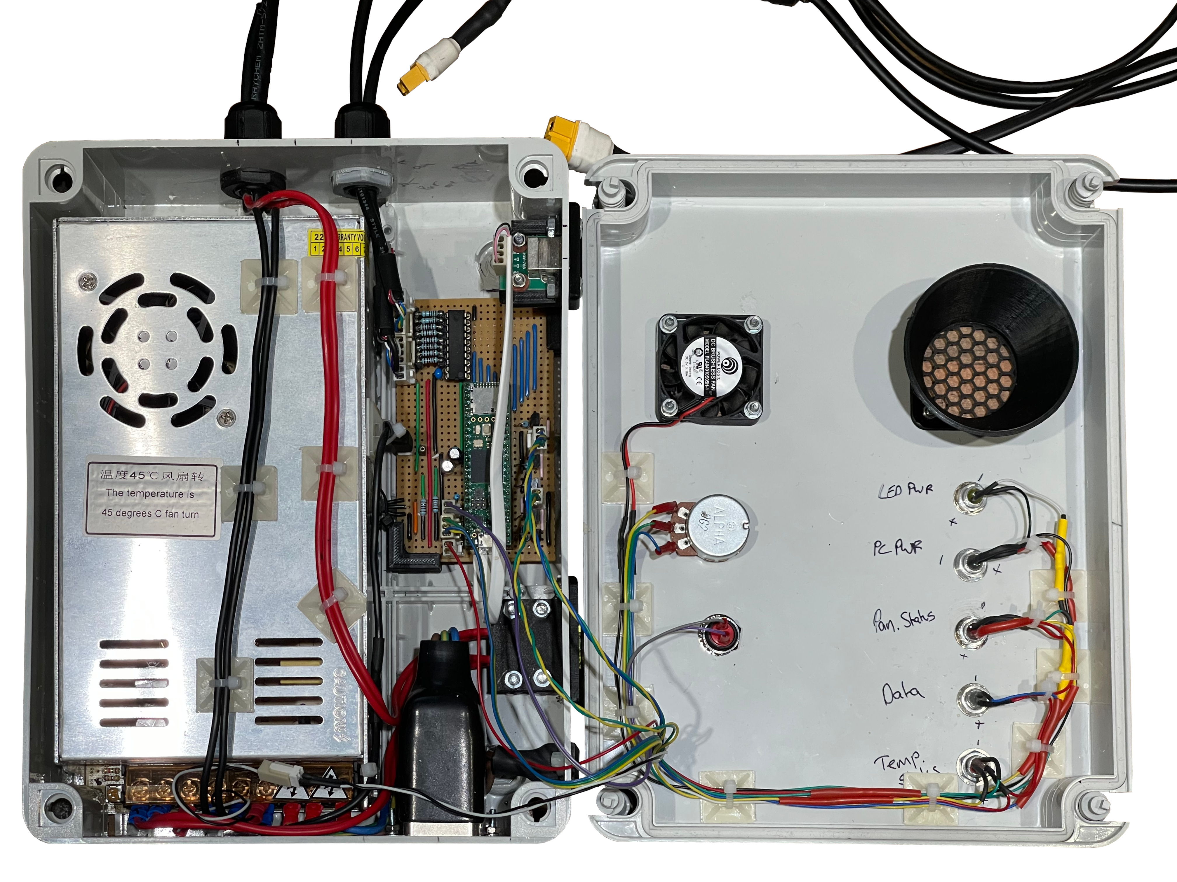
Packaging It Up
The idea is to have a “control box”, which houses the PSU and the Microcontroller board as an all-in-one centre for the Matrix Panels. The main factor governing the size of the control box is the size of the PSU. Now, I don’t know if you have ever tried to look for a suitable enclosure for a project, but I find that it can be blooming difficult sometimes and time consuming! Are those internal dimensions? Are those external dimensions? Gah! I eventually settled on a Gewiss Surface Mounted Plastic Enclosure, part number GW44208. It has external dimensions of 254 × 200 x 98 mm, and internal dimensions of 240 × 190 × 90 mm.

On the face of it, this is big enough for the PSU, however it has noggins (correct term?!) in the corners for the lid screws to go into - this means that the PSU cannot butt-up right to the edge. All is not lost though - I realised that I can cut a notch out of one of the noggins, and modify the connector-end of the PSU to be able to fit the PSU in nicely, since it is below the screw depth. This is more clear in the following photo of the PSU mounted in the enclosure:

Microcontroller Board
With the PSU fitted in the enclosure, I now need to squeeze in board that has the Teensy 4.1, and associated support circuitry. I’ll break it down:
Output Buffer
As previously mentioned, the Teensy 4.1 is a 3.3 V device, so its GPIO outputs are 3.3 V at logic high output. The WS2811 Pixels take 5 V, and in general, require a 5 V logic data signal. If we go into nitty gritty detail, the WS2811 IC is specified to have a VIH minimum of 0.55VDD. VIH minimum is the threshold at which the input is registered as a logic high input. So, when VDD = 5 V, VIH minimum = 0.55 × 5 V = 2.75 V. So, technically, the WS2811 ICs will handle a 3.3 V logic input, but, there is only 0.55 V of headroom there - I’m not happy with that.
To solve this, I need to convert the 3.3 V logic out of the Teensy 4.1 to 5V logic. I decided to use a TI SN74HCT541 Octal Buffers and Line Drivers with 3-state Outputs. Why this? Well, it can operate on supply voltages between 4.5 V to 5.5 V, for registering logic high inputs, the threshold is VIH minimum = 2 V, so the 3.3 V logic output from the Teensy comfortably surpasses that. For registering logic low inputs the threshold is VIL maximum = 0.8 V, the logic low output of the Teensy 4.1 should be pretty close to 0V and will never be anywhere near that threshold.
How about the output? Well, the WS2811 datasheet defines the data in pin as consuming only 1 μA. (I’m not sure how much I believe this, since that would mean the input impedance is 5 MΩ! Hmm.) Well, taking it at face value, when the output current of the buffer is 20 μA or less:
VOH = 4.4 V min @ 20 μA
VOL = 0.1 V max @ 20 μA
… That’s much better! The logic high output is guaranteed to be at least 4.4 V, and in reality, probably much closer to 5 V, since the stated values are a conservative minimum. I will have the enable pins permanently asserted, so the 3-state output functionality is not used. I absolutely love this choice of buffer by the way, it’s classic 7400 series logic, it’s been around since the 60’s. In fact, the datasheet linked was first written in 1996 when I was 5. This is the HCT version, but I suspect the original ‘541 was probably released between the 60’s and 80’s. (I’ll try find out…).
With WS2811 LED Strings that are located away from the data source, the most vulnerable part is the link from the output to the first pixel, and indeed this project fits this mould. The outputs from each pixel are buffered outputs from the WS2811, and the wire distance between each pixel is the same, and short. So, we need to ensure that the data that reaches the first pixel does not suffer from any signal integrity issues. Admittedly, the signal is quite slow when compared to high speed links where signal integrity is a real concern, so there is not as much danger, however signal integrity issues still can cause problems. Having the output buffered to be 5 V logic certainly reduces potential signal integrity issues, however it may be necessary to have low value impedance matching resistors in-line with the outputs to help balance out any signal integrity issues. I was not sure if this would be needed or not, so I decided to design them in using single in-line sockets, so that I could observe the input data at the first pixel on my oscilloscope both with and without impedance matching resistors, and make the call whether they are needed or not.
Status LEDs
I decided to put some status LEDs on the control box. These being:
- Status - Red/Green LED
- Temperature Status - Red/Green LED
- Data - Blue LED
- Matrix Power - Green
- Microcontroller Power - Green
The latter two are sourced from power rails, but the first three will be driven by the Teensy, i.e. five outputs. The Teensy GPIO pins cannot output the required current for the LEDs, so will need buffering. I decided to use some NPN transistors that I had in my box of bits, allowing me to wire these LEDs up with common anode to the 5V rail. Standard 2N3904 NPN transistors are used, with 1k on the base input.
Panel Detect Functionality
This is a nifty feature that I decided to add in - I had some spare cores in the data cable, so I decided to make it so that the microcontroller can detect which panel is connected to each output plug, since they’re both the same. It’s quite simple really, there are two analogue inputs that are pulled low by a 1k resistor. These two input lines go to the panels. One of the panels has this line to 5 V via a 1k resistor, meaning this panel will cause a 2.5 V reading (Remember, the Teensy is a 3.3V device so we cannot put more than 3.3V into an input). The other panel has the line to 5 V via a 3k resistor, meaning this panel will cause a 1.25 V reading. If the connector is not connected to a panel, 0 V will be read.
Temperature Readback
Temperature could be a concern in this control box enclosure - I can mitigate this with vents and fans should it be a problem, but I thought it was a good idea to put in some way of measuring the ambient temperature in the control box. Two reasons for this; during development and testing, I can use it to keep an eye on the temperature and make amendments as necessary. The second reason, is one that I hoped I would not need, but if temperature was a real problem, then I could add functionality in the code to throttle down the brightness should the temperature be too high, to reduce the demand on the PSU. Speaking of brightness control…
Brightness Control
The LED Pixels are quite bright! The brightness of the pixels can of course be controlled in firmware, but I did not want to hard-code this as a fixed value. A brightness control seemed a good idea. This is implemented very simply! I will have a rotary potentiometer that is connected across 3.3V and 0V (5V is a no no!), and the wiper of the potentiometer is readback on an analogue input. This analogue readback can then be used to scale a brightness variable.
User Button
I did not see any need for a button on the control box, but I did not know if I may want one for a future upgrade to the firmware (for some feature I haven’t thought of yet). To make sure that future-me likes present-me, I added a push button into the design. It won’t do anything, but it is there just in case! I decided to utilise the built-in pull-up on the GPIO pin to save me from needing to add a pull-up/pull-down resistor on the board. The button simply connects between the input and 0V.
Board Design
I wanted to keep costs down on this project, so I decided against having a PCB made, and instead use stripboard. I had limited space available in the control box enclosure now that the PSU is fitted, so I measured what was available and designed with this constraint. To plan the stripboard, I used DIYLC - I’ve been using this for the last 15 years, and honestly it has never let me down. For me, planning and preparation of stripboard always results in really neat and tidy designs, that usually work first time! I’m quite proud of that to be honest.

The following table shows the pins that are utilised on the Teensy 4.1 for the functionality discussed:
| Pin No. | IO No. / Net | Special Function Used? | Connected to |
|---|---|---|---|
| 1. | GND | - | GND / 0V |
| 2. | 0 | GPIO Out | Status Green LED |
| 5. | 3 | GPIO Out | Status Red LED |
| 10. | 8 | GPIO Out | Temperature Status Green LED |
| 13. | 11 | GPIO Out | Temperature Status Red LED |
| 19. | 27 | GPIO Out | Data Activity LED |
| 21. | 29 | GPIO Out, Direct DMA Write | WS2811 Ch. 1 |
| 22. | 30 | GPIO Out, Direct DMA Write | WS2811 Ch. 2 |
| 23. | 31 | GPIO Out, Direct DMA Write | WS2811 Ch. 3 |
| 24. | 32 | GPIO Out, Direct DMA Write | WS2811 Ch. 4 |
| 25. | 33 | GPIO Out, Direct DMA Write | WS2811 Ch. 8 |
| 26. | 34 | GPIO Out, Direct DMA Write | WS2811 Ch. 7 |
| 27. | 35 | GPIO Out, Direct DMA Write | WS2811 Ch. 6 |
| 28. | 36 | GPIO Out, Direct DMA Write | WS2811 Ch. 5 |
| 34. | GND | - | GND / 0V |
| 36. | 14 | A0 | Panel Detect 1 |
| 37. | 15 | A1 | Panel Detect 2 |
| 42. | 20 | 1-Wire Bus | DS18B20 Temperature Sensor |
| 44. | 22 | GPIO In, Pull-up enabled | User Button |
| 45. | 23 | A9 | Brightness Pot Readback |
| 46. | 3.3V | - | R22 Pull-up for DS18B20 & Brightness Pot |
| 47. | GND | - | GND / 0V |
| 48. | Vin | 5V In | MCU Power LED, Via R21 |
The Board Exists
Built the board to my plan, no troubles there. For the connectors, I used Molex KK254 type connectors. I love those, I use them all the time. Have a selection of them to hand at all times!
The Teensy 4.1 isn’t soldered directly to the board, since that’s silly. The Teensy sits in a header socket.

That brings me to a nice stopping point, in the final post in this series, I go into the firmware, software, and finalisation - check it out in Part 3: Firmware, Software & Showtime.